Excuse the pun, but the original wiring was shocking! Old and brittle looking with many frayed wires, loose connectors and bodged junctions.
I decided that it had to be renewed and could have bought a new loom from Hitchcock's. However, I had also decided that I wanted to upgrade the bike to have indicators and subsequently that I was going to fit electronic ignition and a modern regulator/rectifier so, to use another pun, I bit the bullet and decided to make my own loom. How hard could it be?
I'm no electrician, but with my O-level physics could understand the basics of volts, watts, amps and ohms. Fundamentally, the original wiring on the standard bike is quite simple, although there is a certain complexity about it in terms of the emergency start facility, which powers the ignition circuit directly from the alternator in the event of a flat battery.
As I said above, I'd decided to go for electronic ignition and I also decided to renew the original rotor and alternator stator to newer higher output items. This was all to try and build in some reliability. Electronic ignition meant that I needed to upgrade to a 12v system. It also meant that the emergency start facility was pointless (opps another pun!), as electronic ignition needs a good power supply to start, so that simplified the wiring again. The final significant change that I made was to modify the circuit so that all the lights were on the "switched" side, to prevent me leaving them on and draining the battery (see "electronic ignition needs a good power supply to start" above).
In the event, I ended up replacing every single element of the electrical system apart from the lighting switch, headlamp bulb fitting and the speedo bulb fitting.
I broke down the project into four different areas:
- Charging & Ignition
- Power Supplies
- Lighting
- Indicators
For each area, I designed a stand alone circuit diagram to try and simplify and clarify things as I built it. I used Microsoft Visio for this because it was what I knew but could have hand drawn them or used Word etc. One thing I love is that I have been able to save the final wiring diagrams as pdf files and have them on my phone for reference in the event of a roadside incident.
All of the necessary wiring and connectors etc were purchased from
Vehicle Wiring Products. Their range and service was exceptional. I decided to use the original wiring colours as far as possible and also to use the original style bullet connectors and soldered joints etc.
The soldering was a bit of a learning curve, but I think it was all good, as far as I've been able to test. A multimeter is really good to have to check circuit continuity etc as you go along. Basically, I did something and then tested it in isolation before moving on. Also, investing in a decent wire stripper was a good move - it got a lot of use.
Incidentally, I think it cost about the same overall to make my own loom as to buy a replacement one, but mine is "right for the bike" now. It probably took me about four days of "shed time". If I can do this, anyone can!
Charging & Ignition
I had already fitted the original points system (with new points and condensor) and alternator, with a view to converting the alternator to 12v.
I suddenly had a little bit of spare cash (after selling a couple of guitars!) and decided to invest that in the electronic ignition and alternator. With the old kit removed, and comparing the old and new alternators and rotors, it just LOOKS more reliable!
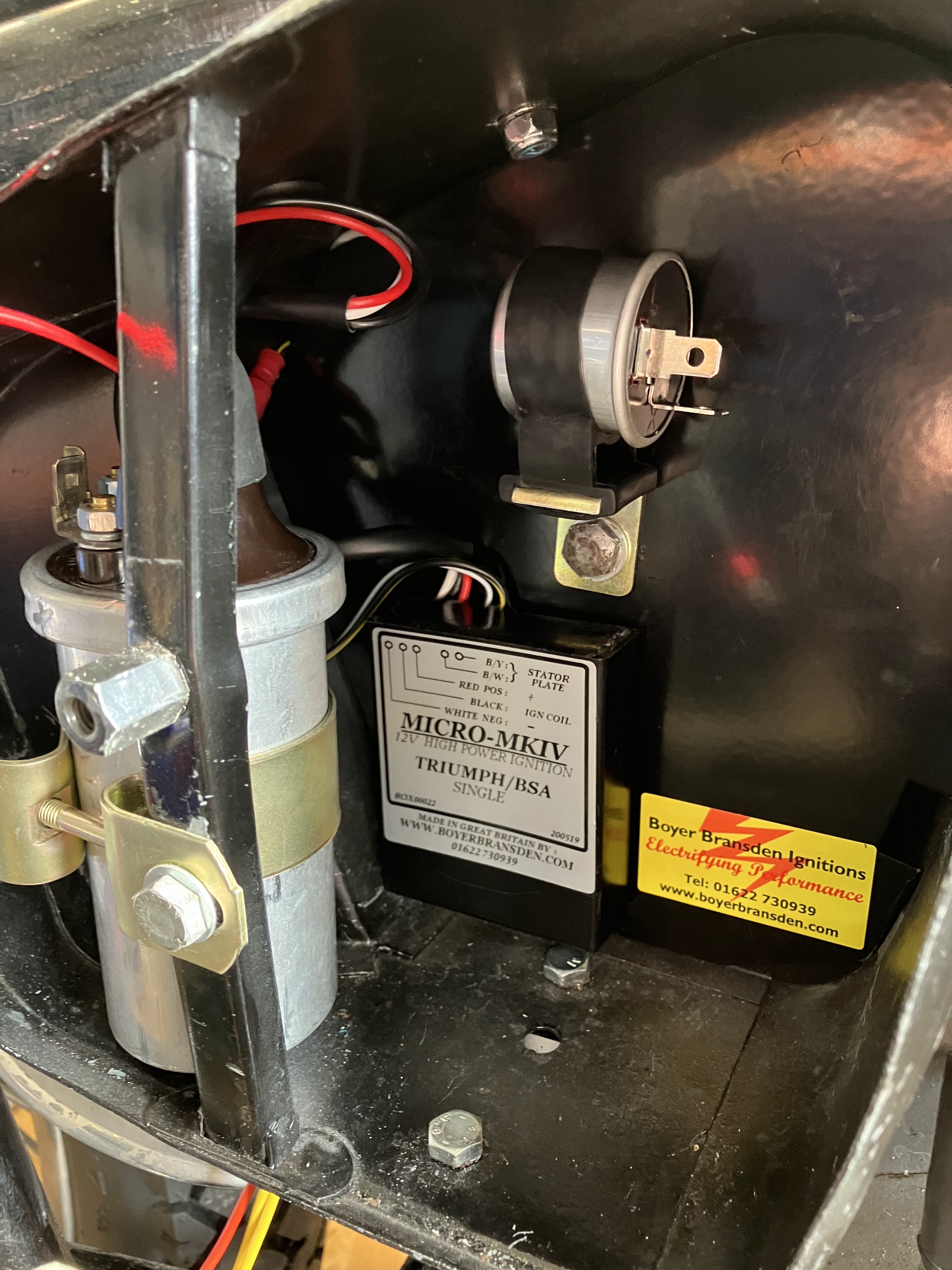
New kit installed ready to be wired up.
New 12v coil and the Boyer Bransden ignition module. Note: although the BB module says it's for Triumph and BSA singles, Hitchcock's provide some extra bits and instructions for use with the Crusader 250s.
I also fitted a modern "solid state" regulator/rectifier, again to try and improve reliability. The unit I used was the A Reg One.
Armed with wiring instructions for the Boyer Bransden and Reg/Rec, I converted that into this diagram for the charging and ignition system.
Power Supplies
A major upgrade in terms of the power supplies has been to add fuses to each power circuit. I used modern blade fuses because they are much more positive in how they locate in to the holder. I did look at adding a 3 or 4 way fuse block but there just wasn't room so I used individual fuse holders. They are the black blocks on this photo.
I fused three circuits separately: main circuit including lighting and horn (15A fuse); stop light circuit (5A fuse) and indicator circuit (5A fuse). There are various internet sources to advise how to choose a fuse size. I may steadily reduce these in practice and see how low I can reliably go!
Note that the bike is positive earth. That's the first time I'd come across positive earth and I had to keep reminding myself not to think "negatively" out of habit! (Hmm - is that saying something about my character?)
I decided to add a specific earthing circuit (reliability again) but haven't shown that on the wiring diagrams. It is the red circuit you can see in the photos.
Lighting
I replaced the pilot lights with LED fittings and must say that they give off a really distinctive bright light. I may also upgrade the headlight to LED at some point, but for now just installed a new 12v bulb. As mentioned earlier, I changed the wiring so that the lighting is all off the switched side of the ignition switch, to try and prevent a flat battery, as I do like to ride with lights on.
You can see the yellow return wires from the LED pilot lights linking in to the red earth circuit here and also the retained headlamp connector.
You can just see that the speedo is lit up here!
Indicators
As a child that started motorcycling in the late 70s, I can't contemplate riding using hand signals, so I had taken an early decision to add indicators to the Crusader. I picked up a nice set from Hitchcock's that are Lucas replica lamps and I think they are quite in keeping. I remember seeing similar lights on 70s Triumphs and BSAs, so not quite the right era but not far off.
I modified a couple of small right angle brackets to mount the front indicators from the fork leg lower yoke pinch bolts. They were subsequently painted black.
There were already two holes in the side of the rear light unit, which I enlarged to take the indicator arms.
I reckon that is a pretty "factory" look. Not original, but that's not what I've been aiming for.
I felt an urge to fit the tank and seat to see how it was all looking!
The kit included a period style switch. The left hand control is a little "busy" with the horn and dip switch as well. I did try a more modern RE combined switch unit, but it just looked wrong on this age of bike, so I went back to the more traditional style.
I mounted the flasher relay in the right hand tool box next to the coil.
I mounted a repeater lamp for each side in the headlamp nacelle.
And the end result of all of that was....
...and on the ignition side ....
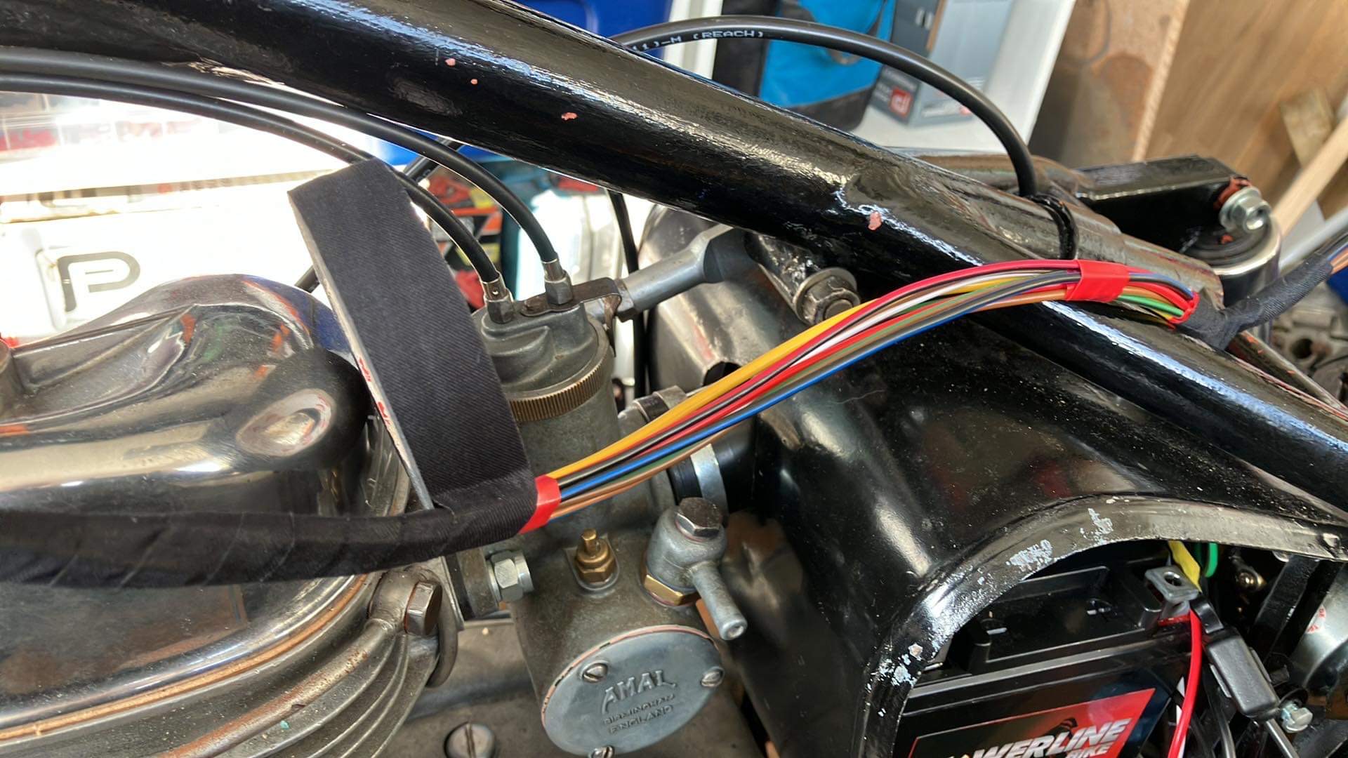
With all of the wiring complete, there was a maze of spaghetti that needed tidying.
I made up a specific loom to join the rear lights via the mudguard to the battery box area.
Then I wrapped all of the different areas using self-amalgamating tape (i.e. it sticks to itself but not the wiring so much - much neater than using PVC insulation tape.
The rat's nest inside the headlamp shell. For the first time ever on a bike though, it all makes sense to me!
And the finished headlamp area with speedo installed.


No comments:
Post a Comment