Sunday 13 February 2022

Engine 1 - Preparation

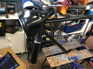
After spending so much time on the cycle parts, I fancied a change from painting things black! Also, as my workshop is so small, I really need to free up some floorspace currently taken up by engine and 3 boxes of assorted engine parts. So it made sense to move on to the engine rebuild next. That way, I can reinstall it in the frame and free up some space. 

A bit of history to set the context: when I bought the bike, I was told that it had been taken off the road about 40 years ago to have engine work undertaken but then never put back together. I received the engine loosely bolted together and loads of bits in various boxes. As an example, the crankshaft and gearbox content were out in loose assemblies. The conrod was in a box of assorted bits.

Once I started to look over it, it became apparent that most of the engine reconditioning work had been done already all those years ago. So the crank has been reground and new bearing shells fitted to the con rod, together with a new little end bush and new gudgeon pin. There's a new +30thou piston and rings and the barrel has been rebored. There was even a gasket set there waiting to be used. All of that lot appears to be still in good condition, even after 40 years of storage.

So that's the good bit. The bad bit is that all of the rest of the engine parts are a complete jigsaw and a lot of it covered in 40 years' grime and surface rust. In most cases, the rust isn't deep enough to damage the parts, but obviously I don't want to rebuild the engine in that condition, so there is lots of deep cleaning required.


I have no idea whether all of the engine parts are there or not. It is just a massive jigsaw, but I have the various workshop manuals and parts lists etc to help me!

Also, I have never completely rebuilt an engine before! I've stripped top ends and barrels and I've dealt with clutches etc but never split a crankcase or rebuilt a gearbox. How hard can it be!

I thought I'd start with the big bits! The crank and gearbox/clutch assemblies were already out in separate units so that seemed as good a place to start as any. 

I pulled the gearbox shafts and clutch apart, taking LOTS of photos and notes about which way it went together.


All of the parts were scrubbed in solvent, inspected and then the surface rust removed using a wire brush in the pillar drill. A list of new parts was started! 

All of the gears looked fine with little wear and no obvious damage. The mainshaft bearing was seized, but I'd already decided that I was going to replace all of the bearings anyway after seeing the state of the crank roller bearing!

The clutch came apart fine and again looked in fairly good condition after a good clean. New friction plates went on the shopping list. I think I'll fit a new drive sprocket as well, mainly because it will be a bit of a pig to get to if I have to do it in 12 months time.

The crank looks to be in really good condition. I gingerly stripped back the masking tape covering the reground pin and it looked great once 40 year old goo from the tape had been cleaned off. 

I pulled out the plugs in the sludge trap and there was very little sludge to clean out, so I'm guessing it was done a long time ago.

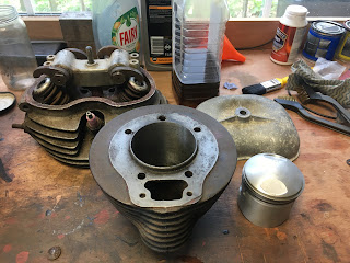
So moving on to the engine block, all I had done up to this point was lift the head off when I first got it (mainly to see if I could find a piston!)


With the barrel removed, I found that the piston had already been fitted with a new ring set - it's all ready to go. The cylinder is freshly honed, but has a very slight amount of surface rust, which will come off with some gentle application of fine emery paper and oil.


The cylinder head and barrel were filthy. I was going to send them to be vapour blasted, but needed to degrease them first. As I was doing that, I watched 40 years of grime come away from the surface and they are in surprisingly good condition. I'm going to spray the barrel black and just clean up the head. I also have a spare head which looks to be in better condition again but I won't make a decision on which to use until I've stripped them down.


Then it was time to split the case for the first time. I was really pleased with what I found:


I gave everything a really good clean and inspection and Scotchbrited the outer faces. Although good, they weren't without issues, mostly on the left hand primary case, where a number of the threaded holes for attaching the outer case had either stripped threads or, in the case of the two that sit in the drive chain tunnel, had been drilled out, presumably following damage. This is apparently a common thing, after people put a case screw in that's too long and it then gets damaged by the chain flapping against it.

So I am helicoiling three holes along the bottom of the case:


The two chaincase holes are slightly more complicated. I need to make up a couple of "bosses" to take 1/4" BSF case screws:


I've done helicoiling before and not too worried about that. But the bosses were something else - I ended up doing some very rudimentary and agricultural machining to form those. Basically, I got two 1/4" BSF nuts and also a matching bolt. I cut the head off the bolt and screwed one of the nuts onto it, then used the bolt as a shaft to mount the nut in my pillar drill. I moved the drill table up until I could use a file against the rotating nut to "machine" down the body of the nut to form a shoulder, but leaving about 2mm of hexagon as a flange. The pictures show it better than words really:


Then I drilled out the case to suit the diameter of the rounded part of the nut and epoxied it in to the case from behind.


Et voila - the threaded hole is restored! I was very pleased with myself at doing this - felt like I was channelling previous generations of Shearer engineers!


The final part of "cleaning/preparation" of the cases was to make sure that all of the internal oil passages are clear. I followed the excellent engine rebuild article by Jack Gray for this and it was good at the end of it to see fresh engine oil ooozing around the engine's veins and arteries!!

A nice (and also expensive) box of new engine bearings, seals and filter parts arrived so, once the helicoiling is done, we are ready to start rebuilding.

The most tedious part of the build so far has been to go through the boxes of grubby bits, cleaning and degreasing every last nut bolt and washer and then getting rid of any surface rust using the wire brush and pillar drill. But it's great that I now have a whole pile of clean stuff that may or may not have a part to play in the rebuild! What I have realised is that there are up to 3 engine's worth of certain parts so I have a few to play around with to get the best of the bunch.


A Rolling Chassis!


What a great moment it is when your project is back on her own two wheels - I of course couldn't resist sitting across the frame and making appropriate engine noises!


My workshop is very small and suddenly became much more congested with the wheels on. I spotted a castor base thing in Aldi and thought it might help me make the frame a bit more manouverable. 

First I marked out and cut a slot in the base for the rear tyre to sit into.


Then I added a couple of pieces of 3" x 2" to grip the wheels a bit.


It kind of works although I can't rely on it to hold the bike upright. Definitely helps move around the workshop though. You can see the bike sat in it on the first photo.


Wheels - 4; New Bearings, Brakes and Tyres

I pretty much just followed the manual to replace the wheel bearings. 

But I did have a few little issues. Firstly, I hadn't realised that there are actually 3 bearings in the back wheel - 2 in the hub and another in the QD sprocket carrier / brake. I had to wait for (yet another!) parcel delivery.

On the back wheel, I struggled to get the second hub bearing out. There is a distance piece between the two bearings and a cutout which should let you get a drift onto the inner race of the second bearing but I just couldn't get enough purchase/force onto it that way (it has been sat there for probably 60 years!)

My solution was to use a "Rawlplug" Expanding masonry bolt - by inserting it through the bearing and then expanding it I could then get a drift onto the back of the bolt and drive it out from the other side - worked a treat!


The final issue I had was that the front bearings can bind up if the inner race is preloaded against the hub. This happened to me and the tip I got from one of the forums was to undo the retaining nut and tap the axle on the opposite side - this just eased the bearing back off the shoulder and stopped it binding.

I haven't really done much refurbishment of the brakes; just serviced them really, making sure that all of the pivots and operating arms were free to move and greased up etc.  Obviously I took all the precautions about old brake dust etc as I was stripping and cleaning them. 

The brake linings are still quite thick, so I'm going to see how they perform before I decide whether to fit new linings or not. It may be an early upgrade! The drums are also in good condition so I just cleaned those up.

More work was needed on the rear. The brake drum is in a unit with the rear sprocket and also includes the cush drive rubbers. This allows the rear wheel to be removed from the bike (e.g. to repair a puncture) while the unit stays attached to the swinging arm and you don't have to touch the chain and brake adjustments etc. The sprocket teeth still have some life left in them so I'm leaving for now, but cleaned up everything and repainted. The cush drive rubbers are 60 years old so I concluded that they probably wouldn't have much "cush" left in them and fitted new ones!


I also reinstalled the brake light switch on the frame and have fitted a new brake lever pivot. I think the original was probably bent in an "off" and had been replaced by a motley collection of bolts, washers and nuts!

"QD" brake/sprocket unit reinstalled in the swinging arm.


Cheap tyres are available in "classic" tread patterns and sizes, but I decided to go for something decent and ordered Avon Speedmaster (front) and Safety Mileage II (rear). These use the original tread pattern but I think a more modern rubber compound. They get good reviews anyway. A(nother) nice parcel arrived.


New rim tapes were installed and the tyres went on OK. After the trauma of my last attempt at fitting new tyres some years ago, I did a bit of You Tube research this time before I started! The secret in my case was to slightly inflate the inner tubes first and fit them into the tyre BEFORE you start to get the first side bead onto the rim. After that, it's mostly a case of making sure that the beads are well down into the well of the rim to make sure that you have as much bead to play with as possible when you are levering the last part on.

I've seen videos showing that you might need to inflate to high pressure to seat the beads correctly, but mine seem to be evenly located looking at the lines around the tyre wall. If necessary, I can look at that once on the road.

I like this photo comparing the old and new wheels:


The shed has been painted since I started as well!!


Wheels - 3; Truing

Now that I had the frame in a state where I could fit the wheels, I could true up the rims - i.e. get them to turn in proper circles and with no side to side buckles.

The method I used was a bit unorthodox, but worked fine. First I mounted the front wheel in the forks:

Then I clamped a piece of scrap wood across the fork legs and marked this up with the lines that each side of the rim needed to follow when it was true horizontally. I also set the vertical position of the wood at the point where any vertical run-out was maximum.


I chose to tackle the vertical run-out first; not sure why but it just seemed instinctively right to get that done first! The method I used was to identify where the maximum run-out was and then slacken spokes opposite to that and tighten corresponding spokes 180 deg around from there. i.e. in the diagram below, if the rim was high in quadrant A compared to quadrant B, I tightened spokes in A and loosened in B. The adjustments were no more than 1/4 turn at a time and you kind of develop a "feel" for what to do. As the rim came into true, I adjusted the piece of timber down and eventually it was pretty much there but not quite, as the horizontal "buckles" also impacted on the rim height.

So, moving on to the horizontal adjustments, opposing pairs of adjacent spokes were tightened/loosened, again using no more than 1/4 turn at a time. I had to move backwards and forwards between vertical and horizontal truing a couple of times to get it there. At the end I was within about 1mm, which looked OK to me.

As a final check, I made sure that the spokes were all roughly similar tension by "pinging" them with a screwdriver - very technical!

I followed the same process on the rear wheel, but clamped the wood across the shock absorbers.


Finally, I checked that none of the spokes were protruding above the nipples (which could cause a puncture). I found one very slight protrusion and filed it down.

One thing worth mentioning was that I found both rims had a built in "fault" where they had been welded together. The width of the rim at this point was about 1-2mm less than the rest of it and actually there was also a vertical dip as well. Nothing I did to the spoke tension could take that out. I'm assuming it will be OK in practice.


Frame Rebuild

 At last, time to start putting things back together again!

In readiness for the frame rebuild I polished up the fork sliders, using the same process as the hubs - successively finer grades of Scothbrite pads followed by successively finer wet and dry paper and then Solvol polish. They came up really nicely.

The first photo shows before and after of the two legs. This was also really the point where I started the degreasing and cleaning up of the multitude of nuts, bolts and studs using a wire brush attachment in the pillar drill. Where possible, I'm trying to reuse as many of the fixings as I can, not only to save money, but because I think it will end up more in keeping as a whole look. Remember this is a bike to be used, not a museum piece.


Both legs looking nice - I had to replace one of the studs. 


I also cleaned up the various fittings for the headset bearings and the fork shrouds. The bearing races look in pretty good condition. I replaced the ball bearings, but again didn't get sucked in to automatically upgrading to taper roller bearings. I may do that in the future, but only if I find the original set-up lacking.


With the bearing races tapped back into the frame, it feels like the rebuild has commenced!


In swift succession, the swinging arm (complete with new bushes) was installed and then the new Armstrong shock absorbers fitted. These aren't exactly the same as would have been fitted originally, as they have exposed springs, but also aren't out of character with the bike and were way cheaper, as they were second hand but unused.


You can see my very makeshift, but surprisingly effective, workstand here with the frame clamped onto my Workmate!

Next up was to install the head bearings, stem and headlight nacelle...


... followed by the fork shrouds, fork legs and handlebars.


A quick aside here. When I painted the black bits, I used Plasticote for the nacelle and Halfords Spray Enamel for the fork shrouds. I reall wasn't very happy with the finish on the nacelle - it just didn't have the same deep gloss as the shrouds. After a few days of agonising, I decided that I wouldn't grow to like it any more as time went by, so I dismantled the front end again and gave the nacelle a few extra top coats of the gloss enamel. It looks much better now ☺.

Next up was the toolbox:


And now of course the wheels could go on. Starting to look a bit like a bike again now!